

Introduction to Automated Test Workflows
Modern power electronics testing demands high precision, repeatability, and efficiency. As product complexity increases, manual testing methods become a bottleneck, introducing the risk of human error and making traceability difficult to maintain. Building an automated data acquisition system is the most effective way to address these challenges, enabling engineering teams to capture high-resolution measurements while synchronizing multiple instruments in real time.
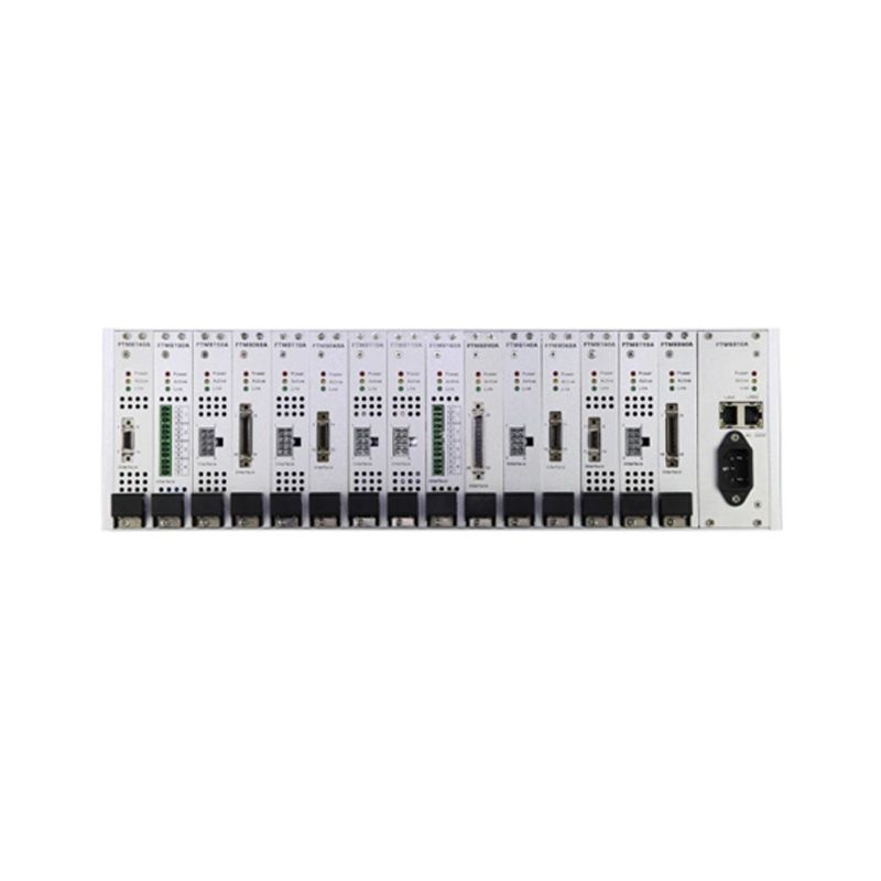
By centralizing control and data logging, organizations can reduce test setup times and ensure that every data point is fully traceable. This guide explains how to integrate the FTM8000 series modular automated data acquisition and control system with power testing equipment to establish robust, automated test workflows.
Core Components of the Test Architecture
A well-designed automated test environment relies on the seamless interaction of several key components. The foundation of this architecture is a flexible controller capable of interfacing with various instruments and sensors. The FTM8000 series modular automated data acquisition and control system serves as this central hub, providing the modular architecture necessary to scale channel counts and input types as test requirements evolve.
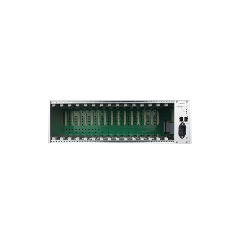
When configuring the architecture, engineers must consider three primary layers:
- Signal Routing and Conditioning: Interfaces that manage voltage and current levels, ensuring safe and accurate signal transmission from the device under test (DUT) to the measurement hardware.
- Data Acquisition and Control: The core FTM8000 system, responsible for digitizing analog signals, executing control loops, and communicating with external instruments via standard industrial protocols.
- Software and Data Management: The top-level application layer that defines test sequences, logs data, and generates compliance reports.
Because the FTM8000 is modular, test engineers can mix and match measurement types—such as thermocouples, strain gauges, and high-voltage inputs—within a single chassis. This flexibility is crucial when integrating diverse power testing equipment, such as programmable AC/DC sources, electronic loads, and power analyzers, into one unified workflow.
Integrating Power Testing Equipment
The integration phase is critical for creating traceable, automated test workflows. Power testing often requires precise timing between the application of electrical stimulus and the capture of the resulting measurements. To achieve this, the automated data acquisition system must act as both the measurement engine and the test sequence coordinator.
Step 1: Hardware Connectivity
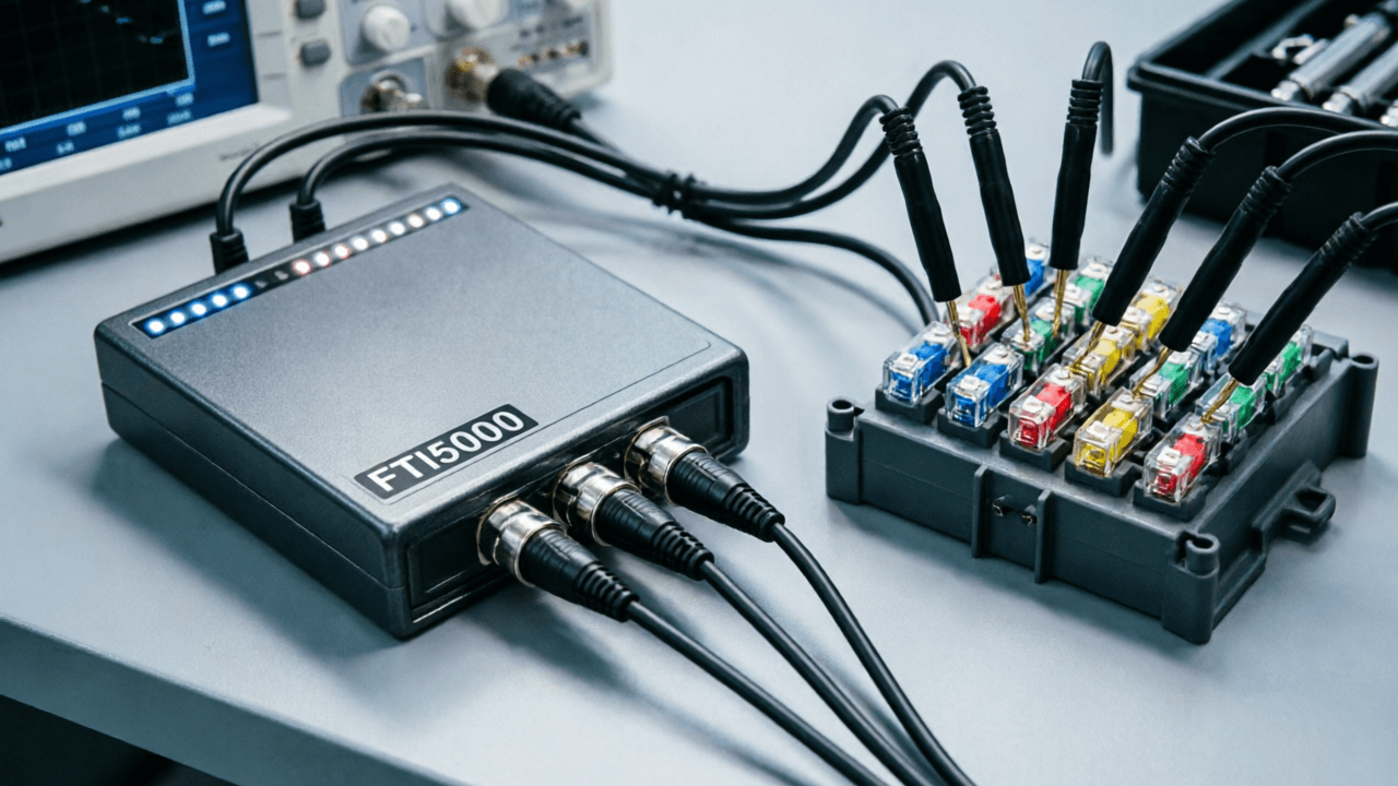
Begin by physically connecting the power testing equipment to the FTM8000. Utilize the system’s digital I/O and analog output modules to trigger external instruments, such as electronic loads or power supplies. For measurements, route the voltage and current signals from the DUT directly into the FTM8000’s high-resolution analog input modules. This direct integration minimizes signal degradation and ensures that the controller has immediate access to the data required for pass/fail criteria.
Step 2: Communication Protocol Setup
Establish communication between the FTM8000 and the power testing equipment using standard interfaces like Ethernet, CAN, or RS-485, depending on the specific requirements of the connected instruments. The automated data acquisition system must be configured to poll the external equipment for status updates and measurement data at defined intervals, ensuring all measurements are time-stamped and synchronized across the entire test setup.
Step 3: Workflow Automation and Sequencing
With hardware and communications established, the final step is to define the automated test sequence. Using the FTM8000’s control capabilities, engineers can program complex sequences—such as ramping a power supply to a specific voltage, applying a load step, and simultaneously logging the DUT’s thermal and electrical response. Because the FTM8000 manages both the control and the data acquisition, the resulting dataset is inherently synchronized, guaranteeing high traceability and eliminating the data alignment issues common in multi-instrument setups.
Best Practices for Traceable Test Environments
To maximize the value of an automated data acquisition system, organizations must prioritize data integrity and system scalability. Traceability requires that every measurement can be linked back to the exact test conditions under which it was captured. By using the FTM8000 as a unified controller, all data—whether generated internally by the DAQ modules or externally by connected power testing equipment—is logged into a single, time-aligned file structure.
Furthermore, the modular nature of the FTM8000 ensures that the test environment is future-proofed. As testing requirements expand to include higher channel counts or new sensor types, additional modules can be integrated into the existing chassis without requiring a complete system redesign. This approach not only protects capital investment but also ensures that automated test workflows remain adaptable to evolving industry standards and product specifications.