Voltage headroom disappears
At sub-1V rails, cable, busbar and contact resistance can consume the entire voltage available to the load.

FaithTech designs and manufactures programmable DC power supplies and electronic loads for energy, industrial, automotive, electronics, and aerospace applications.
Copyright © 2026 FaithTech
AI POWER RAIL / VRM / FUEL CELL TESTING
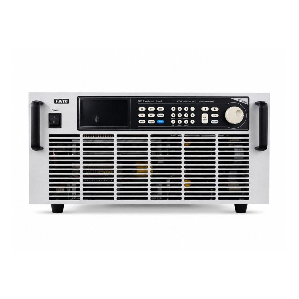
Apply full rated current where ordinary electronic loads run out of voltage headroom. FaithTech NZ/N loads reproduce sub-1V, kiloamp operating points for GPU and CPU power rails, VRMs, fuel-cell cells and production ATE.
0.2V
FULL CURRENT
5,000A
MAX MODEL
20A/µs
SLEW RATE
0.2V @ 5,000A
Full-current operating point
-2.4V @ 1,200A
NZ active voltage support
Up to 20A/µs
Current slew rate
300W–15kW
Product-family power range
THE REAL LIMIT
At 1,000A and above, milliohms matter. The load, interconnect and measurement architecture must be designed as one electrical loop.
Operating envelope
Illustrative comparison at a 1,000A test point
The real DUT voltage must also cover voltage drop across busbars, cables, contacts and protection hardware.
At sub-1V rails, cable, busbar and contact resistance can consume the entire voltage available to the load.
GPU, CPU and VRM rails require repeatable current steps that expose droop, recovery and protection behavior.
Low-inductance connections, remote sensing, synchronized acquisition and fixture design directly affect the result.
MODEL LADDER
Selected N-series configurations provide full-current operation at 0.2V. Values shown are individual published model configurations, not combined family maxima.
| Model | Current | Power | Full-current point | Height |
|---|---|---|---|---|
| FT68203N-20-1000 | 1,000A | 3kW | 0.2V @ 1,000A | 3U |
| FT68206N-20-2000 | 2,000A | 6kW | 0.2V @ 2,000A | 5U |
| FT68209N-20-3000 | 3,000A | 9kW | 0.2V @ 3,000A | 12U |
| FT68212N-20-4000 | 4,000A | 12kW | 0.2V @ 4,000A | 12U |
| FT68215N-20-5000 | 5,000A | 15kW | 0.2V @ 5,000A | 12U |
Each row is an individual published configuration. Current, voltage and power ratings must be checked against the selected model and waveform.
TEST ARCHITECTURE
A correct load selection can still produce misleading results if the busbar, remote sensing, trigger path and acquisition system are not configured for the target edge rate.
Sub-1V rail or fuel-cell output
Short current path and remote sense
0.2V full-current loading
Waveform capture, triggers and reports
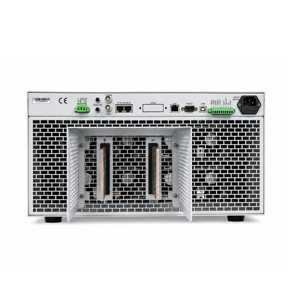
Use remote sensing at the DUT connection point.
Keep the high-current loop short, wide and mechanically secure.
Specify pulse width, duty cycle and repetition rate, not only peak current.
Coordinate triggers with an oscilloscope or suitable acquisition system for edge measurements.
APPLICATION PATHS
Start with the electrical operating point, then add the fixture, measurement, channel count and automation required by the application.
Reproduce sub-1V, kiloamp load conditions for Vcore rails, multiphase VRMs, PMICs and accelerator power modules.
Load low-voltage electrochemical sources without losing the operating point in test-loop resistance.
Turn engineering profiles into repeatable automated checks for low-voltage converters and power modules.
DYNAMIC PERFORMANCE
Dynamic capability must be evaluated together with fixture inductance, model rating and the requested pulse profile.
20A/µs
Current slew rate
20kHz
Dynamic test frequency
4 modes
CC / CV / CR / CP
Sequence
Programmable test profiles
TEST-NODE SELECTION
The products complement each other. Select by electrical node, not by product family alone.
Board / rail level
For sub-1V power rails and electrochemical sources where full current at minimal voltage is the defining requirement.
PSU / rack / HVDC level
For higher-voltage, higher-power AI PSU, HVDC bus, power shelf, rack burn-in and scalable regenerative loading.
WHY FAITHTECH
Selected N models maintain full current down to 0.2V.
Choose published 1,000A through 5,000A configurations.
Coordinate load, busbar, sensing, measurement and automation.
Support AI power rails, fuel cells, power modules and production ATE.
ENGINEERING FAQ
A load may have a high current rating but still be unable to draw that current from a 0.2V rail. The complete current path must provide enough voltage to overcome the load minimum operating voltage plus cable, busbar and contact losses.
N configurations are designed for full-current operation down to 0.2V on selected models. NZ configurations add active voltage support for operating points that extend below 0V, with published configurations reaching -2.4V at 1,200A.
Yes. The platform supports programmable dynamic loading, sequence testing and current slew rates up to 20A/µs. The achievable waveform at the DUT also depends on fixture inductance, cabling and the selected model.
A system can be configured with multiple loads, remote control, measurement and trigger coordination. Share the rail count, timing relationship and current profile so the correct control architecture can be selected.
No. NZ/N is optimized for ultra-low-voltage, kiloamp test nodes such as GPU rails, VRMs and fuel-cell cells. FTR7000 is intended for higher-voltage, higher-power PSU, HVDC bus, rack and megawatt-scale regenerative testing.
Provide the minimum DUT voltage, maximum current, power, number of rails, expected current slew rate, pulse duration, duty cycle, connection distance and required measurements.
CONFIGURATION REVIEW
Share minimum voltage at the DUT, maximum current, dynamic profile, pulse duration, number of rails and connection distance. FaithTech engineers will recommend the correct load, fixture and measurement configuration.