

Introduction to Battery Fault Simulation Testing
Modern power electronics and battery management systems (BMS) require exhaustive validation to ensure operational safety and reliability. While standard charge and discharge cycle testing verifies normal operation, engineers must also validate how their devices respond to adverse electrical events. Battery fault simulation testing bridges this gap by allowing developers to safely replicate real-world failure scenarios without the risk of catastrophic thermal events associated with physical battery faults.
The FT9350 Series Comprehensive Battery Emulator is engineered specifically to meet these rigorous validation demands. Equipped with a proprietary fault simulation function, the FT9350 allows engineers to seamlessly transition from standard power emulation to complex fault condition replication. By simulating scenarios such as battery disconnection, short circuits, and reverse polarity connection, test engineers can comprehensively evaluate the protective mechanisms of their devices under test (DUT).
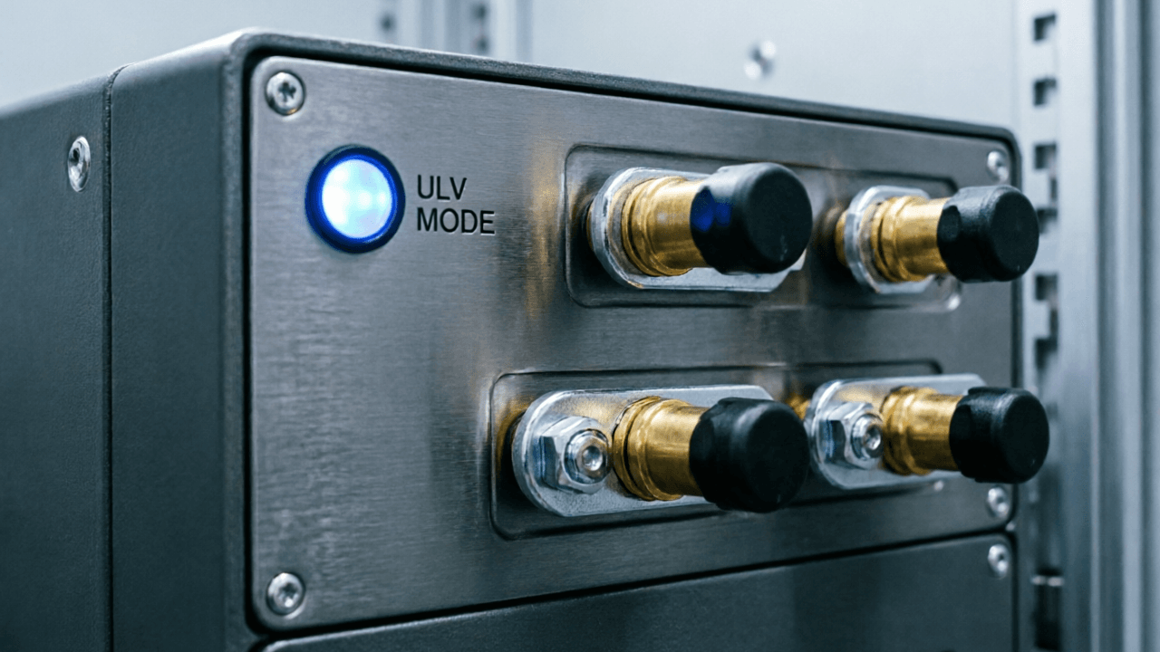
Preparing the FT9350 for Safe Fault Injection
Before initiating any fault simulation, proper configuration of the FT9350 is essential to ensure both operator safety and accurate test results. The emulator features a 4.3-inch high-definition LCD display and supports both local and remote control modes, providing flexibility in test bench setups.
To prepare the system for battery fault simulation testing, follow these baseline steps:
- Isolation Verification: Ensure galvanic isolation is maintained between channels. The FT9350 supports multi-channel series configuration, making proper isolation critical when executing faults across stacked battery modules.
- Interface Selection: Connect your preferred control interface. The emulator is equipped with LAN, RS485, and CAN control interfaces, with native support for SCPI and Modbus communication protocols. For automated fault testing sequences, LAN combined with SCPI is highly recommended.
- Baseline Parameter Setting: Configure the baseline voltage and current parameters. The FT9350 boasts a voltage accuracy of up to 0.01% F.S. and features three current measurement ranges with seamless auto-switching, ensuring that the baseline state is precisely defined before a fault is triggered.
Simulating Short Circuit Faults
Short circuits are among the most dangerous battery faults, potentially leading to excessive current draw, thermal runaway, and structural damage to the DUT. Simulating this safely requires a power source capable of instantaneously altering its output state while accurately logging the DUT's response.
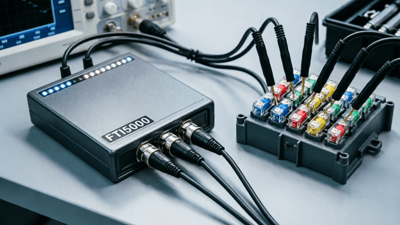
To execute a short circuit simulation using the FT9350:
- Establish the Baseline: Set the emulator to the normal operating voltage of your battery pack. Ensure the DUT is in its standard operational state.
- Configure the Fault: Access the proprietary fault simulation menu via the local LCD or send the corresponding SCPI command via the remote interface. Select the short circuit condition.
- Execute and Monitor: Trigger the short circuit state. The FT9350 will safely collapse the voltage to simulate a direct short. Utilize the emulator's μA-level measurement capability to monitor the DUT's standby or shutdown power consumption immediately following the fault injection. This precise measurement is critical for verifying that the DUT's protection circuits have successfully isolated the power path.
- Recovery Testing: Clear the fault condition and monitor the DUT's recovery behavior. The seamless auto-switching of current measurement ranges ensures that the transition from high-current fault states back to μA-level static states is captured without data loss.
Replicating Reverse Polarity Connection Faults
Reverse polarity connection occurs when a battery is connected with its positive and negative terminals reversed relative to the DUT. This fault can severely damage unprotected electronics, blow fuses, or trigger permanent failure modes. Validating reverse polarity protection circuits is a crucial phase of battery fault simulation testing.
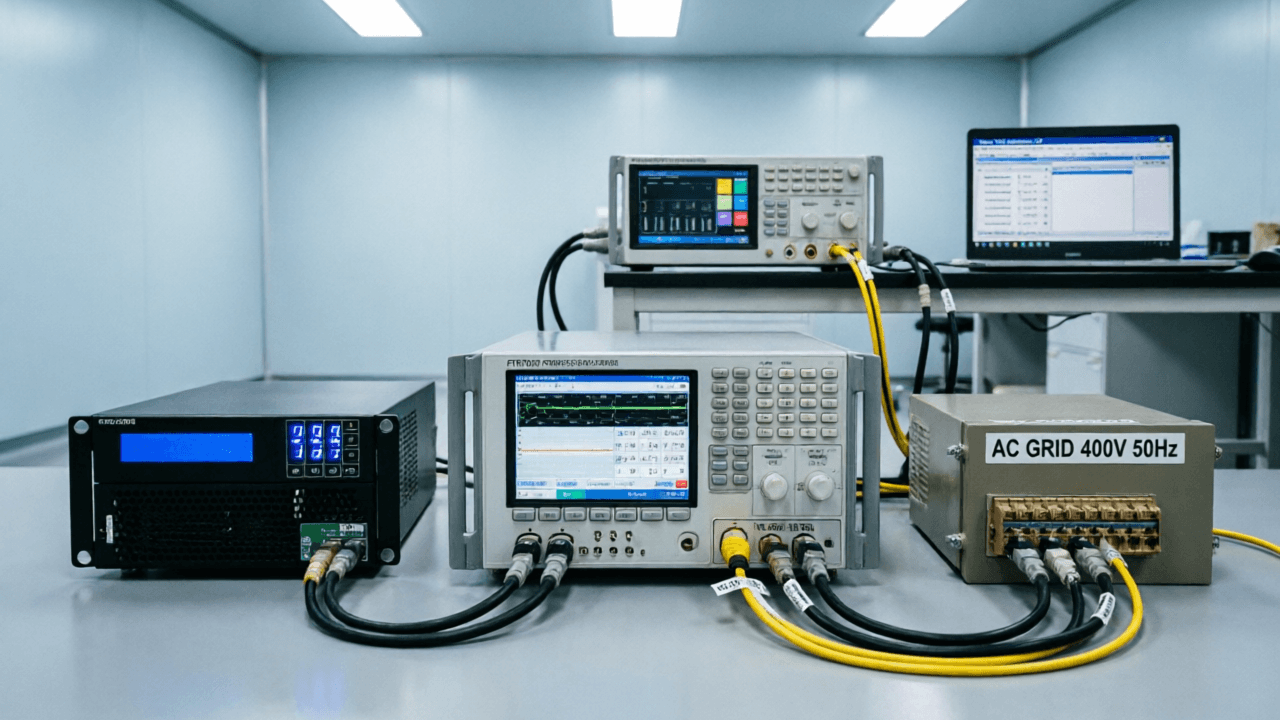
The FT9350 simplifies reverse polarity validation through its integrated fault simulation functions. Use the following workflow to test your DUT's reverse polarity protection:
- Baseline Operation: Confirm the DUT is functioning normally with the correct polarity applied from the FT9350.
- Initiate Reverse Polarity: Using either the 4.3-inch local display or a remote SCPI command over the LAN interface, command the FT9350 to enter the reverse polarity fault state. The emulator will safely invert its output voltage.
- Analyze DUT Response: Observe the DUT's protection mechanisms. A properly designed system should block reverse current flow, blow an input fuse, or activate a blocking diode. The FT9350's high voltage accuracy (0.01% F.S.) ensures that the applied reverse voltage is exact, allowing you to determine the precise trigger threshold of any voltage-based protection circuits.
- Data Logging: Utilize the USB interface to export test logs and screen captures. This enables detailed post-test analysis and provides necessary documentation for compliance and quality assurance records.
Conclusion
Comprehensive electronics validation requires testing beyond standard operating parameters. By utilizing the proprietary fault simulation functions of the FT9350 Series Comprehensive Battery Emulator, engineers can safely and accurately replicate critical real-world battery faults. Whether executing a short circuit to verify current interrupt mechanisms or applying reverse polarity to test input protection, the FT9350 provides the precision, control, and safety required for advanced battery fault simulation testing. With its versatile communication interfaces and high-accuracy measurements, it serves as an indispensable tool for modern power electronics validation.