
FaithTech
FaithTech entwickelt und fertigt programmierbare Gleichstrom-Stromversorgungen und elektronische Lasten für Anwendungen in den Bereichen Energie, Industrie, Automobil, Elektronik und Luft- und Raumfahrt.
Urheberrecht © 2026 FaithTech
FaithTech entwickelt und fertigt programmierbare Gleichstrom-Stromversorgungen und elektronische Lasten für Anwendungen in den Bereichen Energie, Industrie, Automobil, Elektronik und Luft- und Raumfahrt.
Urheberrecht © 2026 FaithTech

Wenn ein Netzgerät plötzlichen Laständerungen ausgesetzt wird, kann sein Ausgangswert momentan vom Nennwert abweichen. Die Messung der dynamischen Antwort einer elektronischen Gleichstromlast während eines Transiententests hilft zu überprüfen, ob das Netzgerät, die Last und das Messsystem sich unter schnell wechselnden Bedingungen wie erwartet verhalten. Ziel ist es nicht nur, Spannungs- und Stromwellenformen zu beobachten, sondern diese konsistent genug zu erfassen, um Designrevisionen, Einstellungen und Betriebsgrenzen zu vergleichen.
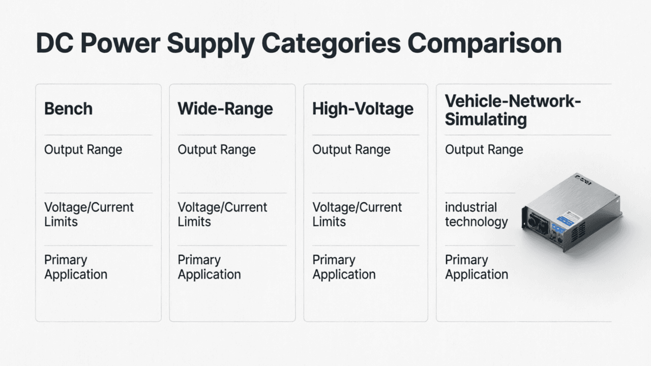
Das dynamische Verhalten beschreibt, wie schnell und sauber ein System von einem Arbeitspunkt zu einem anderen wechselt. Bei der Prüfung von Stromversorgungen kann ein Lastsprung Überschwingen und Unterschwingen der Ausgangsspannung, die Erholungszeit, Oszillationen und die Wechselwirkung mit der Ausgangskapazität aufzeigen. Die elektronische Last ist Teil des Prüfsystems, daher können ihr eigenes Regelverhalten, ihre Eingangskapazität und das Verhalten des Stromregelkreises beeinflussen, was auf der Wellenform sichtbar ist.
Ein klarer Messplan trennt das Verhalten des Prüflings von Artefakten, die durch Fixtures, Tastköpfe oder Lasteinstellungen eingebracht werden. Dies ist besonders wichtig beim Testen von Stromversorgungen, die in empfindlicher Elektronik, Motorantrieben, Kommunikationsgeräten oder batteriebetriebenen Systemen eingesetzt werden, wo kurze Transienten den Betrieb beeinträchtigen können.
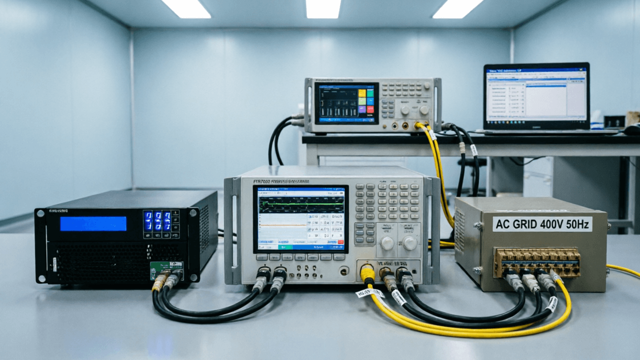
Beginnen Sie mit der Definition der transienten Bedingung: anfänglicher Laststrom, geschalteter Laststrom, Slew-Rate falls steuerbar, Impulsbreite und Wiederholungsrate. Notieren Sie die Ausgangseinstellung der Stromversorgung, die Ausgangskapazität und jegliche Kabelkompensation oder Remote-Sense-Konfiguration. Diese Details sind wichtig, da dieselbe Stromversorgung mit verschiedenen Ausgangskondensatoren, Leitungslängen oder Sense-Punkten unterschiedlich reagieren kann.
Verwenden Sie einen Messpunkt, der die an der Last anliegende Spannung repräsentiert. Wenn Remote-Sense verwendet wird, messen Sie am Sense-Punkt oder am Geräteeingang, nicht nur an den Versorgungsklemmen. Halten Sie Hochstrompfade kurz und verwenden Sie Koaxialverbindungen oder einen kontrollierten Tastpunkt für die Spannung. Für den Strom verwenden Sie eine kalibrierte Stromsonde, einen Shunt oder das Monitor-Signal der Last, wenn dessen Bandbreite und Skalierung bekannt sind. Verbinden Sie die Massebezüge des Oszilloskops sorgfältig, um Masseschleifen oder unbeabsichtigte Strompfade zu vermeiden.
Das Triggern ist kritisch. Verwenden Sie den Trigger-Ausgang der Last, ein Synchronsignal von der Last oder den Flankentrigger des Oszilloskops auf der Stromwellenform. Stellen Sie ausreichend Pre-Trigger-Zeit ein, um den stationären Zustand vor dem Sprung zu erfassen, und ausreichend Post-Trigger-Zeit, um die Erholung zu beobachten.
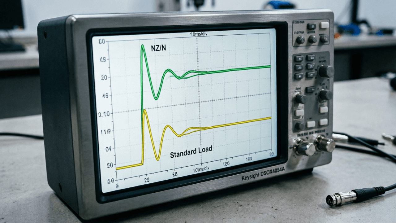
Konfigurieren Sie zunächst die DC-Elektroniklast für den vorgesehenen Betriebsmodus, in der Regel Konstantstrom für Lastsprungtests. Stellen Sie den statischen Lastwert ein und vergewissern Sie sich, dass die Stromversorgung stabil ist, bevor Transienten angewendet werden. Konfigurieren Sie dann den transienten Sprung, einschließlich der hohen und niedrigen Strompegel sowie der Übergangsgeschwindigkeit. Wenn die Last eine einstellbare Slew-Rate zulässt, beginnen Sie mit einem kontrollierten Wert, der der realen Anwendung entspricht, anstatt der schnellstmöglichen Flanke.
Verbinden Sie als Nächstes die Oszilloskop-Kanäle. Messen Sie die Ausgangsspannung mit einer passiven oder aktiven Tastspitze am definierten Messpunkt, und messen Sie den Laststrom mit einer Stromtastspitze oder einem validierten Monitorsignal. Verwenden Sie geeignete Bandbreitenbegrenzungen, falls das Rauschen zu stark ist, dokumentieren Sie jedoch, ob eine Filterung angewendet wird, da diese die beobachteten Spitzenwerte verändern kann.
Führen Sie einen einzelnen Transienten aus und prüfen Sie die Wellenform. Prüfen Sie, dass die Stromstufe sauber ist und der Spannungstransient nicht abgeschnitten wird. Erfassen Sie dann mehrere Akquisitionen, um die Wiederholbarkeit zu bestätigen. Speichern Sie Wellenformdaten, Bildschirmbilder und Testbedingungen. Notieren Sie für die formelle Berichterstattung Folgendes:
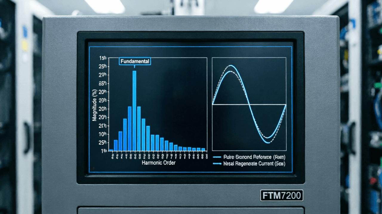
Nach der Erfassung des Transienten wird die Wellenform anhand des Testziels ausgewertet. Zu den gängigen Parametern gehören maximale Spannungsabweichung, Dauer außerhalb der Toleranz, Einschwingzeit in ein definiertes Band und das Vorhandensein von Schwingungen. Definieren Sie das Akzeptanzband vor dem Test, da „eingeschwungen" in verschiedenen Systemen unterschiedliche Bedeutungen haben kann.
Vergleichen Sie Spannungs- und Stromwellenformen miteinander. Wenn der Stromsprung ein Überschwingen oder eine Schwingung zeigt, kann die gemessene Spannungsantwort eher durch die Last als nur durch die Versorgung beeinflusst sein. Lange Leitungen, schlechte Tastkopf-Masseverbindung und unzureichende Sense-Anschlüsse können Ringen oder Offset verursachen. Überprüfen Sie auch, ob die Eingangsnennwerte und die Transientenfähigkeiten der Last für den Test geeignet sind; eine elektronische Last kann Grenzen bezüglich maximalem Strom, Spannung, Leistung und Transientenverhalten aufweisen, die beachtet werden müssen.
Wiederholen Sie den Test unter relevanten Bedingungen: verschiedene Eingangsspannungen, Laststufen, Temperaturen falls erforderlich und Kabellängen, wenn die Anwendung dies erfordert. Ein einzelner Durchlauf bei einem Betriebspunkt kann Grenzverhalten möglicherweise nicht aufdecken.
Ein disziplinierter Ansatz macht die Prüfung des dynamischen Ansprechverhaltens nützlich statt bloß anekdotisch. Durch die Kontrolle des Lastsprungs, die Definition von Messpunkten und die konsistente Aufzeichnung der Bedingungen können Ingenieure fundierte Erkenntnisse über das Verhalten der Stromversorgung gewinnen und das Vertrauen in das transiente Verhalten verbessern.